Im>SilverplateDelta m (Reverted 1 edit by 77.98.33.109 identified as test/vandalism using STiki) |
m (1 revision: Import list 2) |
(No difference)
| |
Revision as of 00:22, 16 June 2016
Template:Use dmy dates Template:Infobox automobile
The Lunar Roving Vehicle (LRV) or lunar rover was a battery-powered four-wheeled rover used on the Moon in the last three missions of the American Apollo program (15, 16, and 17) during 1971 and 1972. It was popularly known as the moon buggy, a play on the phrase "dune buggy".
The LRV was transported to the Moon on the Apollo Lunar Module (LM) and, once unpacked on the surface, could carry one or two astronauts, their equipment, and lunar samples. The three LRVs remain on the Moon.
History
The concept of a lunar rover predated Apollo, with a 1952–1954 series in Collier's Weekly magazine by Wernher von Braun and others, "Man Will Conquer Space Soon!" In this, von Braun described a six-week stay on the Moon, featuring 10-ton tractor trailers for moving supplies.
In 1956, Mieczyslaw G. Bekker published two books on land locomotion.[1] At the time, Bekker was a University of Michigan professor and a consultant to the U.S. Army Tank-Automotive Command's Land Locomotion Laboratory. The books provided much of the theoretical base for future lunar vehicle development.
Early lunar mobility studies
Template:Confusing section

Apollo 16 astronauts in the Earth trainer
In the February 1964 issue of Popular Science, von Braun, then director of NASA's Marshall Space Flight Center (MSFC), discussed the need for a lunar surface vehicle, and revealed that studies had been underway at MSFC in conjunction with Lockheed, Bendix, Boeing, General Motors, Brown Engineering, Grumman, and Bell Aerospace.[2]
Beginning in the early 1960s, a series of studies centering on lunar mobility were conducted under MSFC. This began with the Lunar Logistics System (LLS), followed by the Mobility Laboratory (MOLAB), then the Lunar Scientific Survey Module (LSSM), and finally the Mobility Test Article (MTA). In early planning for the Apollo program, it had been assumed that two Saturn V launch vehicles would be used for each lunar mission: one for sending the crew aboard a Lunar Surface Module (LSM) to lunar orbit, landing, and returning, and a second for sending an LSM-Truck (LSM-T) with all of the equipment, supplies, and transport vehicle for use by the crew while on the surface. All of the first MSFC studies were based on this dual-launch assumption, allowing a large, heavy, roving vehicle.[3]
The LLS studies were begun by Grumman and Northrop in the fall of 1962; these were designs for pressurized cabin vehicles with electric motors for each wheel. At about this same time, Bendix and Boeing were conducting internal studies on lunar transportation systems. Bekker, now with General Motors Defense Research Laboratories (GMDRL) at Santa Barbara, California, was completing a study for NASA's Jet Propulsion Laboratory on a small, unmanned lunar roving vehicle for the Surveyor program. Ferenc Pavlics, originally from Hungary, used a wire-mesh design for "resilient wheels," a design that would be followed in future small rovers.[4]
In early 1963, NASA selected MSFC for studies in an Apollo Logistics Support System (ALSS). Following reviews of all earlier efforts, this resulted in a 10-volume report. Included was the need for a pressurized vehicle in the 6,490–8,470 lb (Template:Convert/roundExpression error: Unrecognized punctuation character "[".Template:Convert/round kg) weight range, accommodating two men with their expendables and instruments for traverses up to two weeks in duration. This was called a Mobility Laboratory (MOLAB).[5] In June 1964, MSFC awarded contracts for MOLAB studies and Mobility Test Articles (MTAs) to Bendix and to Boeing, with GMDRL as vehicle technology subcontractor. Bell Aerospace was already under contract for studies of Lunar Flying Vehicles.[6]
Even as ALSS was underway, MSFC was examining a less ambitious surface exploration activity, the Local Scientific Surface Module (LSSM). This would be composed of a fixed, habitable shelter-laboratory (SHELAB) with a small lunar-traversing vehicle (LTV) that could either carry one man or be remotely controlled. LSSM would be carried on an LSM-T, thus still requiring a dual launch. The Propulsion and Vehicle Engineering (P&VE) support contractor Hayes International made a preliminary study of the shelter and vehicle.[7] Also, for the potential need of a MOLAB-like vehicle in future, enlarged lunar explorations, the MOLAB efforts were continued for some time, resulting in several full-scale MTAs.


Comparison of distances driven by various wheeled vehicles on the surface of Earth's moon and Mars
With pressure from Congress to hold down Apollo costs, Saturn V production was reduced, allowing only a single booster per mission. It would then be necessary for any roving vehicle to be carried on the same Lunar Module as transporting the astronauts. In November 1964, ALSS was put on indefinite hold, but Bendix and Boeing were given study contracts for small rovers under the LSSM program. The name of the Lunar Excursion Module was changed to simply the Lunar Module, indicating that the capability for powered "excursions" away from a lunar-lander base did not yet exist. There could be no SHELAB — the astronauts would work out of the LM — and the LTV accommodating two persons took the name Local Scientific Surface Module (LSSM). MSFC was also examining unmanned robotic rovers that could be controlled from the Earth.
From the start of MSFC, Huntsville, Alabama-based Brown Engineering Company (BECO) had participated in all of its lunar mobility efforts. In 1965, BECO became the prime support contractor for MSFC's P&VE Laboratory. With an urgent need to determine the feasibility of a two-man LSSM, von Braun bypassed the usual procurement process and had P&VE's Advanced Studies Office directly task BECO to design, build, and test a MTA for the vehicle.[8] While Bendix and Boeing would continue with work leading to LSSM concepts and designs, the MTA was vital for MSFC human factors studies involving spacesuit-clad astronauts interfacing with power, telemetry, navigation, and life-support equipment on the rover.
In designing the LSSM MTA, full use was made of all earlier small-rover studies, and commercially available components were incorporated wherever possible. The selection of wheels was of great importance, and almost nothing was known at that time about the lunar surface. The MSFC Space Sciences Laboratory (SSL) was responsible for predicting surface properties. BECO was also the prime support contractor for the SSL and set up a test area to examine a wide variety of wheel-surface conditions. To simulate Pavlics' "resilient wheel," a four-foot-diameter inner tube wrapped with nylon ski rope was used. On the MTA, each wheel had a small electric motor, with overall power provided by standard truck batteries. A roll bar gave protection from overturn accidents.
In early 1966, BECO's MTA became available for examining human factors and other testing. MSFC built a small test track with craters and rock debris where the LSSM and MOLAB MTAs were compared; it was soon obvious that a small rover would be best for the proposed missions. The vehicle was also operated in remote mode to determine characteristics in tests that might be dangerous to the operator, such as acceleration, bounce-height, and turn-over tendency as it traveled at higher speeds and over simulated obstacles. The LSSM performance under one-sixth gravity was obtained through flights on a KC-135A aircraft in a Reduced Gravity parabolic maneuver; among other things, the need for a very soft wheel and suspension combination was shown. Although Pavlics' wire-mesh wheels were not available for the MTA, testing of these was conducted on various soils at the Waterways Experiment Station of the U.S. Army Corps of Engineers at Vicksburg, Mississippi. Later, when wire-mesh wheels were tested on low-g flights, the need for wheel fenders to reduce dust contamination was found. The LSSM MTA was extensively tested at the U.S. Army's Yuma Proving Ground in Arizona, as well as the Army's Aberdeen Proving Ground in Maryland.[9]
Apollo Lunar Roving Vehicle


John Young works at the LRV near the LM Orion on Apollo 16 in April 1972.
During 1965 and 1967, the Summer Conference on Lunar Exploration and Science brought together leading scientists to assess NASA's planning for exploring the Moon and to make recommendations. One of their findings was that the LSSM was critical to a successful program and should be given major attention. At MSFC, von Braun established the Lunar Roving Task team, and in May 1969, NASA selected the Lunar Roving Vehicle (LRV) for use in manned lunar missions and approved the Manned Lunar Rover Vehicle Program as a MSFC hardware development. Saverio F. "Sonny" Morea was named the LRV program manager.[10]
On 11 July 1969, just before the successful Moon landing of Apollo 11, a request for proposal for the final development and building the Apollo LRV was released by MSFC. Boeing, Bendix, Grumman, and Chrysler submitted proposals. Following three months of proposal evaluation and negotiations, Boeing was selected as the Apollo LRV prime contractor on 28 October 1969. Boeing would manage the LRV project under Henry Kudish in Huntsville, Alabama. As a major subcontractor, General Motors' Defense Research Laboratories in Santa Barbara, California, would furnish the mobility system (wheels, motors, and suspension); this effort would be led by Ferenc Pavlics.[11] Boeing in Seattle, Washington, would furnish the electronics and navigation system. Vehicle testing would take place at the Boeing facility in Kent, Washington, and the chassis manufacturing and overall assembly would be at the Boeing facility in Huntsville.[12]
The first cost-plus-incentive-fee contract to Boeing was for $19,000,000 and called for delivery of the first LRV by 1 April 1971. Cost overruns, however, led to a final cost of $38,000,000, which was about the same as NASA's original estimate. Four lunar rovers were built, one each for Apollo missions 15, 16, and 17; and one used for spare parts after the cancellation of further Apollo missions. Other LRV models were built: a static model to assist with human factors design; an engineering model to design and integrate the subsystems; two one-sixth gravity models for testing the deployment mechanism; a one-gravity trainer to give the astronauts instruction in the operation of the rover and allow them to practice driving it; a mass model to test the effect of the rover on the LM structure, balance, and handling; a vibration test unit to study the LRV's durability and handling of launch stresses; and a qualification test unit to study integration of all LRV subsystems. A paper by Savero Morea gives details of the LRV system and its development.[13]


Apollo 15—Lunar Roving Vehicle
LRVs were used for greater surface mobility during the Apollo J-class missions, Apollo 15, Apollo 16, and Apollo 17. The rover was first used on 31 July 1971, during the Apollo 15 mission. This greatly expanded the range of the lunar explorers. Previous teams of astronauts were restricted to short walking distances around the landing site due to the bulky space suit equipment required to sustain life in the lunar environment. The range, however, was operationally restricted to remain within walking distance of the lunar module, in case the rover broke down at any point.[14] The rovers were designed with a top speed of about 8 mph (Template:Convert/pround km/h), although Eugene Cernan recorded a maximum speed of 11.2 mph (Template:Convert/round km/h), giving him the (unofficial) lunar land-speed record.[15]
The LRV was developed in only 17 months and performed all its functions on the Moon with no major anomalies. Scientist-astronaut Harrison Schmitt of Apollo 17 said, "The Lunar Rover proved to be the reliable, safe and flexible lunar exploration vehicle we expected it to be. Without it, the major scientific discoveries of Apollo 15, 16, and 17 would not have been possible; and our current understanding of lunar evolution would not have been possible."[14]
The LRVs experienced some minor problems. The rear fender extension on the Apollo 16 LRV was lost during the mission's second extra-vehicular activity (EVA) at station 8 when John Young bumped into it while going to assist Charles Duke. The dust thrown up from the wheel covered the crew, the console, and the communications equipment. High battery temperatures and resulting high power consumption ensued. No repair attempt was mentioned.
The fender extension on the Apollo 17 LRV broke when accidentally bumped by Eugene Cernan with a hammer handle. Cernan and Schmitt taped the extension back in place, but due to the dusty surfaces, the tape did not adhere and the extension was lost after about one hour of driving, causing the astronauts to be covered with dust. For their second EVA, a replacement "fender" was made with some EVA maps, duct tape, and a pair of clamps from inside the Lunar Module that were nominally intended for the moveable overhead light. This repair was later undone so that the clamps could be taken inside for the return launch. The maps were brought back to Earth and are now on display at the National Air and Space Museum. The abrasion from the dust is evident on some portions of the makeshift fender.[16][17]


The color TV camera mounted on the front of the LRV could be remotely operated by Mission Control in pan and tilt axes as well as zoom. This allowed far better television coverage of the EVA than the earlier missions. On each mission, at the conclusion of the astronauts' stay on the surface, the commander drove the LRV to a position away from the Lunar Module so that the camera could record the ascent stage launch. The camera operator in Mission Control experienced difficulty in timing the various delays so that the LM ascent stage was in frame through the launch. On the third and final attempt (Apollo 17), the launch and ascent were successfully tracked.
NASA's rovers, left behind, are among the artificial objects on the Moon, as are the Soviet Union's unmanned rovers, Lunokhod 1 and Lunokhod 2.
Features and specifications

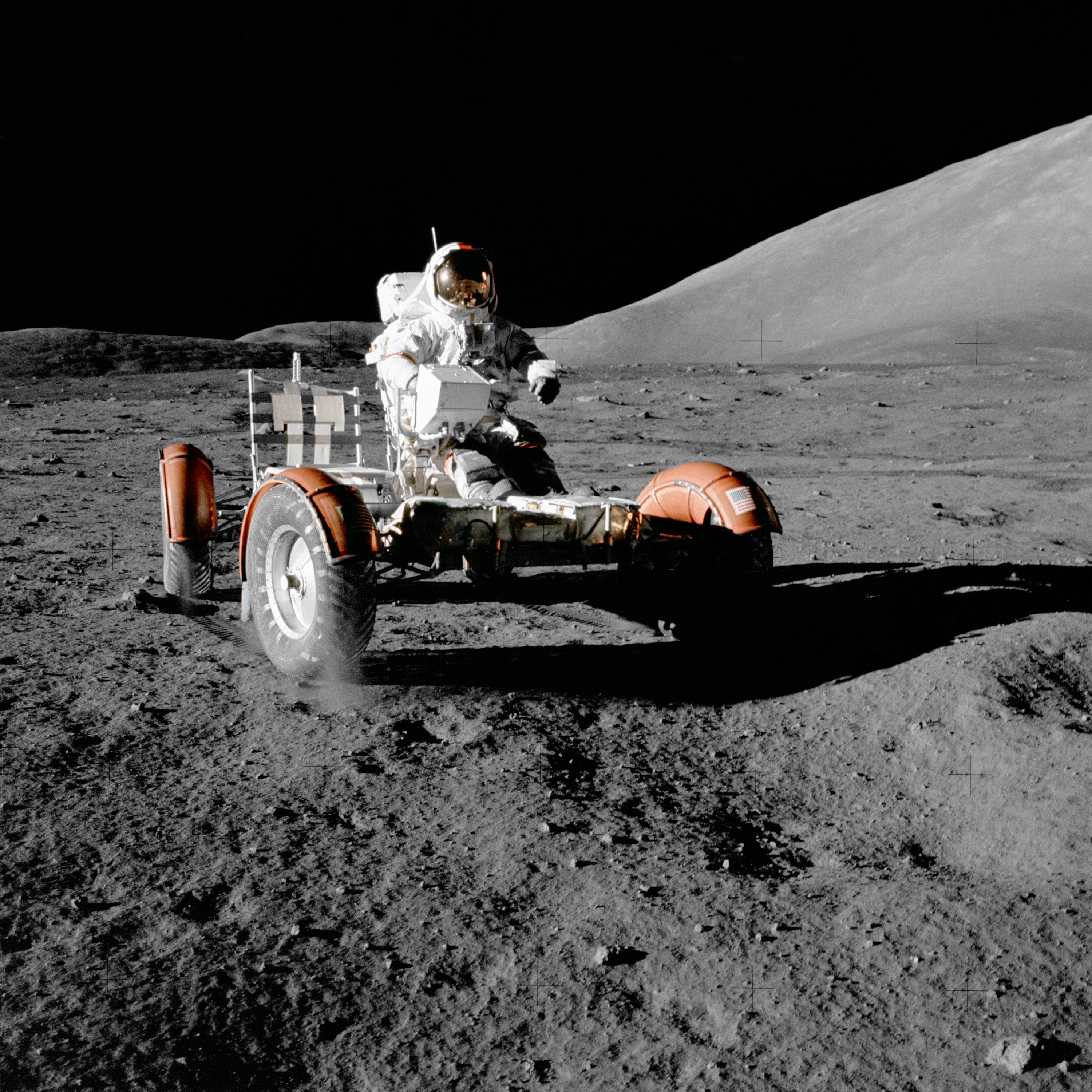
Eugene Cernan test drives the Apollo 17 lunar rover shortly after unloading it from the LM
The Apollo Lunar Roving Vehicle was an electric-powered vehicle designed to operate in the low-gravity vacuum of the Moon and to be capable of traversing the lunar surface, allowing the Apollo astronauts to extend the range of their surface extravehicular activities. Three LRVs were used on the Moon, one on Apollo 15 by astronauts David Scott and Jim Irwin, one on Apollo 16 by John Young and Charles Duke, and one on Apollo 17 by Eugene Cernan and Harrison Schmitt. The mission commander served as the driver, occupying the left-hand seat of each LRV. Features are available in papers by Morea,[13] Baker,[18] and Kudish.[19]
Mass and payload
The Lunar Roving Vehicle had a mass of Template:Convert/round pounds (210 kg), and was designed to hold a payload of Template:Convert/round pounds (490 kg).[20] This resulted in weights in the approximately one-sixth g on the lunar surface of Template:Convert/round pounds-force (35 kgf) empty and Template:Convert/round pounds-force (116 kgf) fully loaded. The frame was 10 feet (Template:Convert/round m) long with a wheelbase of 7.5 feet (Template:Convert/round m). The height of the vehicle was 3.6 feet (Template:Convert/round m). The frame was made of 2219 aluminium alloy tubing welded assemblies and consisted of a three-part chassis that was hinged in the center so it could be folded up and hung in the Lunar Module Quadrant 1 bay. It had two side-by-side foldable seats made of tubular aluminium with nylon webbing and aluminum floor panels. An armrest was mounted between the seats, and each seat had adjustable footrests and a Velcro-fastened seat belt. A large mesh dish antenna was mounted on a mast on the front center of the rover. The suspension consisted of a double horizontal wishbone with upper and lower torsion bars and a damper unit between the chassis and upper wishbone. Fully loaded, the LRV had a ground clearance of 14 inches (Template:Convert/round cm).
Wheels and power


Close-up of wheel showing chevron treads
The wheels were designed and manufactured by General Motors Defense Research Laboratories in Santa Barbara, California.[21] Ferenc Pavlics was given special recognition by NASA for developing the "resilient wheel".[22] They consisted of a spun aluminum hub and a 32 inches (Template:Convert/round cm) diameter, 9 inches (Template:Convert/round cm) wide tire made of zinc-coated woven 0.033 inches (Template:Convert/round mm) diameter steel strands attached to the rim and discs of formed aluminum. Titanium chevrons covered 50% of the contact area to provide traction. Inside the tire was a 25.5 inches (Template:Convert/round cm) diameter bump stop frame to protect the hub. Dust guards were mounted above the wheels. Each wheel had its own electric drive made by Delco, a direct current (DC) series-wound motor capable of 0.25 horsepower (Template:Convert/round W) at 10,000 rpm, attached to the wheel via an 80:1 harmonic drive, and a mechanical brake unit.
Maneuvering capability was provided through the use of front and rear steering motors. Each series-wound DC steering motor was capable of 0.1 horsepower (Template:Convert/round W). The front and rear wheels would turn in opposite directions to achieve a tight turning radius of 10 feet (Template:Convert/pround m), or could be decoupled so only front or rear would be used for steering. They could free-wheel in case of drive failure.
Power was provided by two 36-volt silver-zinc potassium hydroxide non-rechargeable batteries with a capacity of 121 A·h each (a total of 242 A·h), yielding a range of 57 miles (Template:Convert/round km).[15] These were used to power the drive and steering motors and also a 36-volt utility outlet mounted on the front of the LRV to power the communications relay unit or the TV camera. LRV batteries and electronics were passively cooled, using change-of-phase wax thermal capacitor packages and reflective, upward-facing radiating surfaces. While driving, radiators were covered with mylar blankets to minimize dust accumulation. When stopped, the astronauts would open the blankets, and manually remove excess dust from the cooling surfaces with hand brushes.


Lunar Rover diagram. (NASA)


Honorary lunar driver's license presented to then NASA Administrator James E. Webb
A T-shaped hand controller situated between the two seats controlled the four drive motors, two steering motors, and brakes. Moving the stick forward powered the LRV forward, left and right turned the vehicle left or right, and pulling backwards activated the brakes. Activating a switch on the handle before pulling back would put the LRV into reverse. Pulling the handle all the way back activated a parking brake. The control and display modules were situated in front of the handle and gave information on the speed, heading, pitch, and power and temperature levels.
Navigation was based on continuously recording direction and distance through use of a directional gyro and odometer and feeding this data to a computer that would keep track of the overall direction and distance back to the LM. There was also a Sun-shadow device that could give a manual heading based on the direction of the Sun, using the fact that the Sun moved very slowly in the sky.
Usage
Each rover was used on three traverses, one per day over the three-day course of each mission, with the individual performances logged as follows:
| mission | total distance | total time | longest single traverse | maximum range from the LM |
|---|---|---|---|---|
| Apollo 15 (LRV-001) | 17.25 miles (Template:Convert/pround km) | 3 h 02 min | 7.75 miles (Template:Convert/pround km) | 3.1 miles (Template:Convert/pround km) |
| Apollo 16 (LRV-002) | 16.50 miles (Template:Convert/pround km) | 3 h 26 min | 7.20 miles (Template:Convert/pround km) | 2.8 miles (Template:Convert/pround km) |
| Apollo 17 (LRV-003) | 22.30 miles (Template:Convert/pround km) | 4 h 26 min | 12.50 miles (Template:Convert/pround km) | 4.7 miles (Template:Convert/pround km) |
An operational constraint on the use of the LRV was that the astronauts must be able to walk back to the LM if the LRV were to fail at any time during the EVA (called the "Walkback Limit"). Thus, the traverses were limited in the distance they could go at the start and at any time later in the EVA. Therefore, they went to the farthest point away from the LM and worked their way back to it so that, as the life support consumables were depleted, their remaining walk back distance was equally diminished. This constraint was relaxed during the longest traverse on Apollo 17, based on the demonstrated reliability of the LRV and spacesuits on previous missions. A paper by Burkhalter and Sharp provides details on usage.[23]
Deployment
Deployment of the LRV from the LM's Quadrant 1 bay by the astronauts was achieved with a system of pulleys and braked reels using ropes and cloth tapes. The rover was folded and stored in the bay with the underside of the chassis facing out. One astronaut would climb the egress ladder on the LM and release the rover, which would then be slowly tilted out by the second astronaut on the ground through the use of reels and tapes. As the rover was let down from the bay, most of the deployment was automatic. The rear wheels folded out and locked in place. When they touched the ground, the front of the rover could be unfolded, the wheels deployed, and the entire frame let down to the surface by pulleys.
The rover components locked into place upon opening. Cabling, pins, and tripods would then be removed and the seats and footrests raised. After switching on all the electronics, the vehicle was ready to back away from the LM.[24]
Current locations

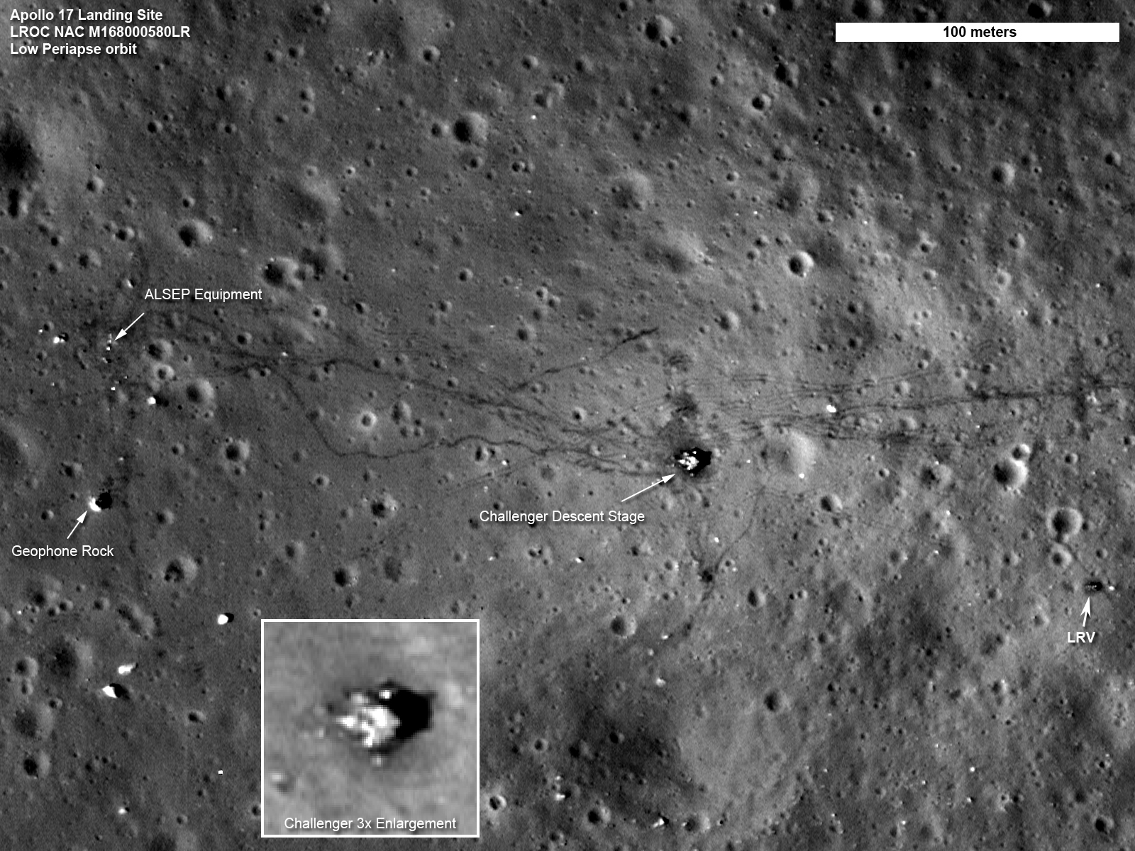
A total of four flight-ready rovers were manufactured. Three were transported to and left on the moon via the Apollo 15, 16, and 17 missions, with the fourth rover used for spare parts on the first three following the cancellation of Apollo 18. Since only the upper stages of the lunar excursion modules could return to lunar orbit from the surface, the vehicles, along with the lower stages were abandoned. As a result, the only lunar rovers on display are test vehicles, trainers, and mock-ups.[25] The rover used on Apollo 15 was left on the lunar surface at Hadley-Apennine ( Template:Coord ). The rover used on Apollo 16 was left on the lunar surface at Descartes ( Template:Coord ). The rover used on Apollo 17 was left on the lunar surface at Taurus-Littrow ( Template:Coord ) and was seen by the Lunar Reconnaissance Orbiter during passes in 2009 and 2011.


Rover replica on display at Epcot
Several rovers were created for testing, training, or validation purposes. The engineering mockup is on display at the Museum of Flight in Seattle, Washington. The Qualification Test Unit is on display at the National Air and Space Museum in Washington, D.C. The rover used for vibration testing is on display in the Davidson Saturn V Center at the Marshall Space Flight Center in Huntsville, Alabama. Additional test units are on display at the Johnson Space Center in Houston, Texas, and the Kennedy Space Center Visitors Complex in Cape Canaveral, Florida.[26] Replicas of rovers are on display at the National Museum of Naval Aviation in Pensacola, Florida, the Evergreen Aviation & Space Museum in McMinnville, Oregon, and the Kansas Cosmosphere and Space Center in Hutchinson, Kansas. A replica on loan from the Smithsonian Institution is on display at the Mission: Space attraction at Epcot at the Walt Disney World Resort near Orlando, Florida.[26][27]
Media
")
References
- ↑ Bekker, Mieczyslaw G.; Theory of Land Locomotion, U. Michigan Press, 1956, and The Mechanics of Vehicle Mobility, U. Michigan Press, 1956 and 1962
- ↑ von Braun, Wernher; “How We’ll Travel on the Moon,” Popular Science, February 1964, pp. 18-26
- ↑ Young, Anthony; Lunar and planetary rovers: the wheels of Apollo and the quest for Mars; Springer, 2007, pp. 30-57; ISBN 0-387-30774-5
- ↑ Bekker, Mieczyslaw G., and Ferenc Pavlics; “Lunar Roving Vehicle Concept: A Case Study”; GMDRL Staff Paper SP63-205, May 1963
- ↑ "Molab," Encyclopedia Astronautics
- ↑ Courter, Robert; “What It’s Like to Fly the Jet Belt,” Popular Science, Nov. 1969, pp. 55-59, 190
- ↑ ”Lunar Shelter/Rover Conceptual Design and Evaluation,” NASA CR-61049, Nov. 1964.
- ↑ ”Brown Builds Concept Of Lunar Vehicle,” BECO Views, Vol. 9, Jan. 1966, p. 1
- ↑ Interviews with Otha H. “Skeet” Vaughan, Jr., MSFC test engineer (retired); also see Vaughan’s "Brief History of NASA Marshall Space Flight Center’s Lunar Mobility Program”; http://www.knology.net/~skeetv/SimHist.html
- ↑ Wright, Mike and Bob Jaques, Editors, Saverio Morea, Technical Editor; “A Brief History of the Lunar Roving Vehicle,” 3 April 2002, MSFC History Office.
- ↑ "Interview with Ferenc Pavlics, lead developer of the Apollo Lunar Rovers"
- ↑ “Lunar Roving Vehicle,” MSFC press release, 29 October 1969; Marshall Star, 3 November 1969
- ↑ 13.0 13.1 Morea, Saverio F.; “The Lunar Roving Vehicle – Historical Perspective”; Proc. 2nd Conference on Lunar Bases and Space Activities, 5–7 April 1988; NASA Conference Publications 3166, Vol. 1, pp. 619-632.
- ↑ 14.0 14.1 “The Apollo Lunar Roving Vehicle”, NASA Document.
- ↑ 15.0 15.1 Lyons, Pete; “10 Best Ahead-of-Their-Time Machines”, Car and Driver, Jan. 1988, p.78
- ↑ NASA Reference Publication 1317, Jan 1994, Sullivan, Thomas A. "Catalog of Apollo Experiment Operations" pg. 68 ”Experimental Operations During Apollo EVAs: Repairs to Experiments,” NASA Document.
- ↑ ”Moondust and Duct Tape,” NASA Document.
- ↑ Baker, David; "Lunar Roving Vehicle: Design Report," Spaceflight, Vol. 13, July 1971, pp. 234-240
- ↑ Kudish, Henry. "The Lunar Rover." Spaceflight. Vol. 12, July 1970, pp. 270-274
- ↑ http://nssdc.gsfc.nasa.gov/planetary/lunar/apollo_lrv.html
- ↑ "Lunar Rover", brochure, Delco Electronics, Santa Barbara Operations,1972
- ↑ "NASA Certificate for Ferenc Pavlics for Inventing the Resilient Wheel" (from Hungarian University of Engineering).
- ↑ Template:Cite journal
- ↑ "The Apollo Lunar Roving Vehicle". NASA. http://nssdc.gsfc.nasa.gov/planetary/lunar/apollo_lrv.html.
- ↑ "The Apollo Lunar Roving Vehicle". NASA. 15 November 2005. http://nssdc.gsfc.nasa.gov/planetary/lunar/apollo_lrv.html. Retrieved 16 May 2010.
- ↑ 26.0 26.1 "Lunar Roving Vehicles". Field Guide to American Spacecraft. http://web.mac.com/jimgerard/AFGAS/pages/rovers/index.html. Retrieved 24 August 2009.
- ↑ Template:Cite news
External links
Template:Commons category
- Boeing Lunar Rover Vehicle Operations Handbook
- Article about the rover
- LRV Operations Handbook, Appendix A (Performance Data)
- Mobility Performance of the Lunar Roving Vehicle: Terrestrial Studies – Apollo 15 Results
- Lunar Rover in Operation Video
- Lunar and Planetary Rovers: The Wheels of Apollo and the Quest for Mars
- Apollo Lunar Roving Vehicle Documentation - Apollo Lunar Surface Journal
Template:Lunar Rovers
| ||||||||||||||||||||
| |||||||||||||||||||||||||||||||||||||||||